


How is a wiring harness created?
The electronic contents inside an automobile are increasing day by day and posing newer challenges in terms of managing the wiring harnesses that connect them.
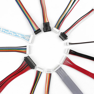
A wire harness is a specially designed system that keeps numerous wires or cables organized. It is a systematic and integrated arrangement of cables within an insulating material.
The purpose of the wiring assembly is to transmit a signal or electrical power. Cables are bound together with straps, cable ties, cable lacing, sleeves, electrical tape, conduit, or a combination thereof.
Rather than manually routing and connecting individual strands, the wires are cut to length, bundled, and clamped to the terminal or connector housing to form a single piece.
The wiring harness is created in two stages. It is designed in a software tool first and then the 2D and 3D layout is shared with manufacturing plants to build the harness.
The specific process of vehicle wiring harness design involves the following steps:
- First, the electrical system engineer provides the functions of the entire electrical system, including the electrical load and related unique requirements. The state of the electrical equipment, the installation location, and the form of connection between the wiring harness and the electrical equipment are all key considerations
- From the electrical functions and requirements provided by the electrical system engineer, the complete vehicle electrical schematic is created by adding components required for a function and connecting them together. The functions which are commonly used across multiple vehicles in an architecture platform are stored together.
- After the schematic is defined, the wiring harness design is created. In one platform, the end customers can have a variety of requirements. It is very time-consuming and expensive if different designs are created for each end user’s requirements separately. So, the designer takes care of the multiple variants while designing the wiring harness.
- At the end, a 2D representation of all the wiring designs is created to show the way different wires are bundled and how the bundles are covered to secure the wires. End connectors are also shown in this 2D diagram.
- These designs can interact with 3D tools for the import and export of details. The wire lengths can be imported from the 3D tool and the end-to-end connection details are exported from the wiring harness tool to a 3D tool. The 3D tool uses these data to add passive components such as straps, cable ties, cable lacing, sleeves, electrical tape, and conduits in relevant locations and send them back to the wiring harness tool.
After the design is completed in software, the wire harness is manufactured in the manufacturing plant starting from the cutting area then the pre-assembly area, and finally in the assembly area.
Post time: May-22-2023